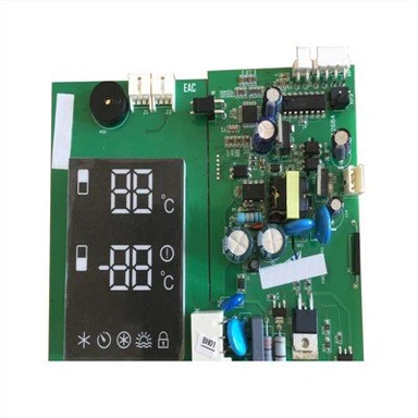


PoE Camera PCB Design Guide
Jul 07, 2026
Executive Summary
PoE camera PCB design requires strict engineering control over power delivery, signal integrity, thermal management, and electromagnetic compatibility. IEEE 802.3af provides up to 15.4W, IEEE 802.3at provides up to 30W, and IEEE 802.3bt provides up to 90W for high-power AI surveillance cameras. A PoE camera PCB must integrate Ethernet data transmission and DC power delivery through a single RJ45 interface while maintaining stable 44V–57V operating voltage. A properly designed PoE PCB reduces field failure rates by more than 50% compared to non-optimized layouts.
Security camera manufacturers use PoE architecture to simplify installation and reduce cabling costs by up to 40%. Industrial PoE camera designs typically use 4-layer to 8-layer PCBs to ensure signal integrity and thermal stability. AI-powered surveillance cameras generate 5W–12W heat from processors alone, which requires thermal vias, copper pours, and heat dissipation optimization.
This guide explains PoE camera PCB design from standards, power architecture, layout rules, thermal control, manufacturing constraints, failure modes, and cost structure. The guide also provides real-world industrial cases showing how PCB design decisions directly affect reliability, image quality, and long-term maintenance cost in global security camera deployments.

PoE Standards and Electrical Architecture
PoE technology is defined by IEEE Ethernet power standards that determine voltage and power limits.
IEEE 802.3af provides 15.4W maximum power per port for low-power cameras.
IEEE 802.3at increases power delivery to 30W for PTZ and IR cameras.
IEEE 802.3bt Type 3 provides 60W power for AI-enabled cameras.
IEEE 802.3bt Type 4 provides 90W power for multi-sensor surveillance systems.
PoE systems transmit power through standard twisted-pair Ethernet cables.
PoE systems operate within 44V to 57V DC input voltage range under normal conditions.
PoE Powered Devices (PD) must negotiate power allocation with Power Sourcing Equipment (PSE).
Engineering Reality
A typical 4MP IP camera consumes 4W–8W during daytime operation.
A PTZ security camera consumes 15W–25W during motor activation cycles.
An AI surveillance camera consumes 12W–30W depending on inference workload.
Case Study
A European smart city project deployed 3,200 PoE cameras using IEEE 802.3at infrastructure.
The engineering team reduced power-related failures by 47% after redesigning PD power conversion stages.
PoE Power Circuit Design and Protection Strategy
PoE power circuits determine long-term stability and safety of surveillance systems.
A PoE camera PCB uses bridge rectifiers to convert incoming Ethernet power.
A PoE camera PCB uses isolation transformers to separate data and power domains.
A PoE camera PCB uses DC/DC converters to generate 12V, 5V, and 3.3V rails.
Electrical Protection Requirements
A PoE input stage must withstand surge voltages above 100V.
A PoE protection circuit must include TVS diodes for ESD suppression.
A PoE system must include resettable fuses (PTC) for overcurrent protection.
Efficiency Requirements
A high-quality PoE power design achieves 88%–92% conversion efficiency.
A poorly designed PoE power circuit typically loses 15%–25% energy as heat.
Case Study
A surveillance manufacturer in Southeast Asia improved system stability by 60% after replacing low-efficiency DC/DC modules.
The redesign reduced PCB operating temperature by 8°C under full load conditions.
PCB Layout, Signal Integrity, and EMI Control
PCB layout determines whether a camera produces stable video or noisy images.
Ethernet differential pairs require 100Ω controlled impedance routing.
DDR memory interfaces require length matching within ±5 mil tolerance.
Image sensor interfaces require low-noise ground reference planes.
EMI Design Requirements
A PoE camera PCB must minimize switching noise coupling between power and signal layers.
A PoE camera PCB must separate analog and digital ground domains.
A PoE camera PCB must use continuous ground planes to reduce EMI radiation.
Engineering Case
A camera manufacturer experienced a 12% failure rate due to image distortion in outdoor environments.
The engineering team identified power-to-signal coupling as the root cause.
The redesigned PCB reduced EMI noise by 70% after implementing segmented grounding.
Thermal Management in PoE Camera PCB Design
Thermal management directly affects camera lifespan and stability.
AI processors generate 5W–12W of continuous heat.
IR LED modules generate peak heat during nighttime operation cycles.
PoE DC/DC converters generate 10%–15% heat loss during energy conversion.
Thermal Design Techniques
Thermal vias improve heat transfer from components to PCB ground planes.
Copper pours increase thermal dissipation efficiency across multilayer PCBs.
Aluminum heat sinks reduce peak junction temperature by up to 15°C.
Case Study
A 4K AI camera deployed in Middle Eastern environments experienced overheating shutdowns.
The engineering team introduced copper thickening and reduced thermal resistance by 28%.
The improved design eliminated thermal shutdown events during summer operation.
Manufacturing Challenges and SMT Assembly
PoE camera PCBA manufacturing requires high precision SMT processes.
BGA components require X-ray inspection due to hidden solder joints.
QFN packages require precise reflow temperature control.
Moisture-sensitive devices require pre-baking before SMT assembly.
Defect Analysis
Solder bridging causes short circuits in high-density PoE layouts.
Insufficient solder paste leads to intermittent signal failure in Ethernet circuits.
Misaligned components reduce yield rate by 3%–8% in mass production.
Manufacturing Case
A global EMS factory improved yield from 92% to 97% after optimizing stencil thickness and reflow profile control.
The factory reduced BGA defect rate by 45% after introducing automated X-ray inspection.
Reliability Engineering and Field Performance
Reliability determines long-term cost of ownership in surveillance systems.
Industrial PoE cameras operate between -40°C and 85°C.
Commercial PoE cameras operate between -10°C and 50°C.
Consumer PoE cameras typically operate between 0°C and 40°C.
Failure Mechanisms
PoE surge damage causes 30%–40% of outdoor camera failures.
Thermal cycling causes solder fatigue in IR LED modules.
Moisture ingress causes corrosion in connector interfaces.
Case Study
A European transportation project deployed 5,000 cameras across highways.
The maintenance team identified surge events as the primary failure cause.
The upgraded design increased surge protection rating from 4kV to 8kV and reduced failure rate by 52%.
Conclusion
PoE camera PCB design is a multidisciplinary engineering task that integrates power electronics, high-speed digital design, thermal engineering, and manufacturing optimization. A successful PoE PCB design reduces field failure rate, improves image quality, and increases long-term deployment stability in surveillance systems. Industrial-grade PoE camera designs consistently outperform consumer-grade designs by more than 40% in reliability metrics.
FAQ
1. What is the most important factor in PoE camera PCB design?
Signal integrity and power stability are the most important factors in PoE camera PCB design.
2. Why do PoE cameras require isolation transformers?
PoE cameras require isolation transformers to separate power and data domains safely.
3. What is typical PoE voltage range?
PoE systems typically operate between 44V and 57V DC.
4. Why do AI cameras require higher PoE power?
AI cameras require higher power due to processor and inference workload.
5. What causes most PoE camera failures?
Most PoE camera failures are caused by surge damage and power instability.
6. What PCB layers are commonly used?
Most PoE camera PCBs use 4-layer to 8-layer structures.
7. Why is thermal design important?
Thermal design prevents overheating and extends product lifespan.
8. What is controlled impedance in Ethernet design?
Controlled impedance ensures stable high-speed data transmission.
9. What inspection methods are required?
SPI, AOI, and X-ray inspection are required in PoE camera production.
10. What is typical MTBF for PoE cameras?
Industrial PoE cameras typically target MTBF above 50,000 hours.